 |
|
Αγωγοί
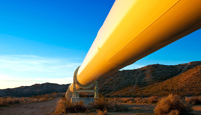
Για την ενεργειακή κάλυψη του πλανήτη, ο άνθρωπος έχει δημιουργήσει χιλιάδες χιλιόμετρα από αγωγούς με σκοπό την μεταφορά καυσίμων στις παραγωγικές μονάδες. Για την σωστή κατασκευή αλλά και τον μετέπειτα έλεγχο αυτών υπάρχουν προηγμένες τεχνικές μη καταστροφικών ελέγχων, μερικές από τις οποίες παρουσιάζονται παρακάτω.
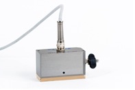
ECA probe
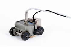
ECA probe mounted in the HydroFORM buggy
Replacement of Traditional NDT Methods with ECA
Eddy current array easily replaces traditional NDT methods such as MPI and PT for surface inspection. ECA provides imaging that is similar to these traditional techniques but with more possibilities. Rejection criteria can be adjusted so that it is based on probe sensitivity, a feature that is unavailable with the traditional methods.
A Variety of Familiar Color-Palette Choices Offering More Possibilities
The MXE 3.0 ECA software features a range of patented intuitive color-palette representations that replicate the look of traditional NDT methods, facilitating the interpretation of ECA signals.
Examples of sensitivity adjustments that can be done using ECA method.
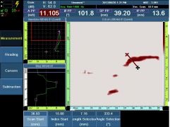
Adjustment of the new MXE 3.0 selection cursors is very intuitive, allowing the user to quickly select any indication.
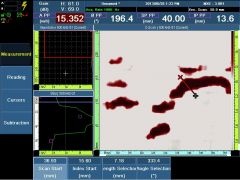
Corrections can be easily done on recorded data. Above example shows gain (contrast) adjustment.
 Ultrasonic thickness gages can provide advantages when a mill operator or end user has to verify wall thickness of a pipe or tube, since measurements are not limited to the accessible ends of the pipe. In the mill, nondestructive wall thickness measurements can be made to detect out-of-tolerance conditions. Concentricity of a continuously formed pipe can be monitored on a constant and automatic basis with no need to cut the pipe or to shut down the manufacturing process. Similarly, when a process requires accurate measurement of thin walled tubing, ultrasonics permits nondestructive thickness measurements along the total length.
Equipment: For manual thickness measurements, the Model 38DL PLUS and 45MG with Single Element software gages provide instant digital readings of typical metal pipes and tubes to a calibrated accuracy of ±0.001 in. (±0.025 mm). These gages, used with appropriate transducers, are capable of measuring most metal tube and pipe walls ranging from less than 0.020 in. to greater than 2 in. (0.50 to 50 mm). Precision gages can also be used with delay line transducers to make thickness measurements to a calibrated accuracy of ±0.0002 in. or ±0.005 mm.
If the diameter of a tube is less than 0.200 in. (5 mm), we recommend the 38DL PLUS or 45MG with Single Element software along with an immersion transducer. The Model RBS-1 Bubbler System is a helpful tool in making ultrasonic thickness measurements that utilize immersion transducers.
Wall thickness measurements on metal pipes or tubes that are badly corroded on either the inside or the outside surface should, as a rule, be made with the Olympus Model 38DL PLUS or 45MG using dual element transducers.
Application
A corrosion inspection solution for axial scanning of pipes using the Olympus HydroFORM with customized gasket plates.
Background
Since its introduction to the pipe inspection market a few years ago, the HydroFORM scanner has proven its worth at tackling corrosion mapping jobs. Thanks to the HydroFORM's innovative water column concept and the use of phased array ultrasonic techniques, inspection rates and data quality and density have improved immensely in relation to conventional UT inspection techniques.
Problem
Ensuring pipe integrity, particularly against corrosion, is a major preoccupation for the petrochemical industry. To make sure that the inspection of pipe systems is reliable and efficient, it is important to have the appropriate tools for the job. When inspecting for corrosion, sometimes only a strip of the pipe needs to be inspected in the axial (longitudinal) direction. For example:
- For smaller pipes that would require overly frequent indexing when scanning circumferentially;
- For pipes with a zone of interest that is concentrated in a specific region on the circumference; or,
- When 360-degree access to the pipe is not possible.
The standard HydroFORM and CHAIN scanner package is a proven solution for circumferential inspections; however, the HydroFORM on its own is not adapted for scanning longitudinally. By using the indexer clicker, or by manually changing the index offset value between scans, it is possible to acquire multiple strips and stack them in the same data file. But, because of beam steering and coupling issues (two aspects that behave quite differently when the probe's primary axis is sitting tangent to the pipe), this application requires some tweaking.
To ensure that the beams hit the surface at due 0 degrees, steering is required. Also, large-pitch and high-frequency probes, such as the standard 7.5L64-I4, are likely to exhibit side lobes, which disrupt the overall S-scan image and leak energy from the main lobe.
If the gasket's curvature radius does not match closely enough to the diameter of the pipe, water leakage is also a problem.
Solution
To overcome these hurdles, a more appropriate phased-array probe can be used in conjunction with curved gasket plates designed for the HydroFORM.
Kit Components
| Part Number | Item Number | Description |
| OMNI2-P2-PA16128 | U8100126 | OmniScan MX2 with 16:128 PA module and NDT SetupBuilder Software (also includes DE15 to Lemo encoder cable adaptor). |
| HydroFORM-SCN | U8750059 | HydroFORM scanner with magnetic wheels and water column (probe sold separately). |
| 5L128-64X7-I4-P-7.5-OM | U8331667 | Application specific PA probe. 5 MHz, 128 element, 0.5 mm pitch, 7 mm elevation with 7.5 m cable and OmniScan connector. |
| CFU03 | U8780008 | Electrical coupling feed unit |
| HydroFORM-A-CurvedPlates | U8775301 | Application specific curved gasket plates kit for 12 to 20 inch OD range, compatible with the HydroFORM. |
| OPTX674 | U8775015 | Indexer Clicker to enabled 2D mapping with only one encoder. Includes a 3-to-one adaptor. All connectors are DE15. |
| OMNI-A-ADP27 | U8780329 | Scanner interface adaptor to link a male LEMO connector to a female DE15 connector. Required to connect the HydroFORM to the Indexer Clicker's 3-to-one adaptor. |
Typical procedure
This specialized application resembles the regular HydroFORM application, but with a few software and hardware differences.
Olympus SetupBuilder software is used to create the focal law configuration and generate a ". law" file which is then imported into the OmniScan for data acquisition (see Figure 1).
Typically, a linear group with an effective aperture of about 4 mm in width (8 elements with the 5L128-I4 phased array probe) is optimal. In most cases, the focal depth can be set to about 2 mm from the interface.
The results in Figure 1 were obtained using a configuration where all incident beams are perpendicular to the surface. The circumferential coverage for this configuration (12.75 inches OD) is around 55 mm from first law to last law. It should be noted that the defects shown at the extremities will look slightly smaller than the ones at the center of the probe because of the narrowing distance between the beams as the skew angle increases.
Diameters between 12 and 20 inches require the use of custom curved gasket plates to ensure proper coupling (see Figure 2). The kit proposed above comprises one gasket plate (nominal 14 in. OD) for pipes from 12 to 16 inches OD, as well as a second gasket plate (nominal 18 in. OD) for pipes from 16 to 20 inches OD.
While the HydroFORM buggy is sitting on a smooth and regular portion of the pipe, the water column is adjusted using the adjustment knob (see Figure 3) so that all focal laws see the pipes interface at 0 mm in true depth. The resulting S-scan shows the interface as being flat.
NOTE: Depending on the orientation of the scanner on the pipes circumference, the HydroFORM bubble management system may perform differently. It may be necessary to move the scanner quickly back and forth on the pipe to help remove bubbles that are trapped in the water chamber before starting the acquisition.
Sensitivity calibration is recommended to homogenize the amplitude of the focal laws, and time-corrected gain (TCG) can be used to compensate for the attenuation in the material, while limiting saturation of the interface echo.
Sensitivity calibration is performed on all focal laws with the aid of the calibration wizard. TCG points are added manually on both the OD and the ID (ideally on a calibration block).
Results
This section presents the results obtained on a 12 in. OD pipe.
Figure 5 represents the corrosion patch mapping in the OmniScan. 121 focal laws correspond to a circumferential strip of about 55 mm (see Figure 1) with a circumferential resolution of 0.5 mm. The maximum PRF for this configuration is 53 mm/s.
Figure 6 shows a 3 mm FBH with a remaining wall of 7.5 mm that has been captured with a very good signal-to-noise ratio.
Conclusion
The HydroFORM scanner can be used to perform axial scans, provided that the following conditions are met:
- The smallest OD in the range is 12 inches nominal.
- Two curved gasket plates are used for ODs ranging from 12 inches to 20 inches (both are included in the kit). Beyond 20 inches, the standard HydroFORM gasket plate can be used.
- The proper focal laws are programmed with Olympus SetupBuilder (.law files).
- OmniScan MXU version is 4.1R6 or later
- The probe that is used has the right pitch and frequency for beam steering according to the pipe diameter.
Introduction:
In today’s pipeline industry, corrosion resistant alloys (CRAs) are widely used to help protect pipelines that transport corrosive fluids. Various combinations of CRA materials and thicknesses are used. In many cases, the parent material of the pipe is carbon steel with a layer of CRA bonded to the inside. The weld that joins pipe segments together is also made of the CRA material.
Challenges of CRA weld inspection
When inspecting a weld with phased array pulse-echo or pitch-catch standard configurations, the ultrasonic beam rebounds at the bottom of the part so that the beam’s second leg passes through the weld bevel and cap area. However, when a CRA is bonded to the inside of the pipe, the alloy often has properties, such as grain structure and velocity, that differ from the pipe’s parent material. The layer of CRA creates mode conversions which make data analysis extremely difficult. To avoid the need of a rebound, a phased array probe with longitudinal waves can be set up to pulse on the opposite side of the weld bevel. However, CRAs are generally more attenuating, which results in a decreased signal-to-noise ratio and, consequently, poor beam penetration. In addition, the upper portion of the weld, with potential surface and sub-surface indications, remains uninspected.
Solution: Dual linear array probes to inspect CRA welds with the PipeWIZARD system
A dual linear phased array (DLA) probe can be fixed to the PipeWIZARD scanner and used to inspect the dissimilar welds (Figure 1). The required equipment includes:
- PipeWIZARD with latest software version (U8110022)
- 4QL15-A27 dual linear phased array probes (Q3300143)
- Two SA27-DNCR-IRC-AODx or SA27-DN55L-FDx-IRC-AODx wedges
- Two PipeWIZARD rings for SA27-IRC wedges (Q1100053)
- Two PipeWIZARD forks for SA27-IRC rings (Q1100054)

Figure 1: Olympus dual linear array probe configuration.
Advantages of the technique
DLA probe with the PipeWIZARD enables the complete and accurate inspection of welds in CRA clad pipelines. The chief advantages of this technique include:
- The benefits of phased array S-scans are combined with low frequency transmit-receive longitudinal (TRL) inspection for better penetration in highly attenuating materials.
- Transmit-receive configuration enables low profile and small foot print wedges to be used, eliminating the need for the wedge damping material and large standoff normally required with longitudinal pulse-echo inspections.
- Signal-to-noise ratio is improved by being able to position the probe closer to the weld, resulting in a shorter UT path.
- The high angle of inspection ensures that the surface and sub-surface areas of the weld are inspected with no back wall rebound.

Figure 2: S-scan imaging of an indication in a CRA weld.
Conclusion
A dual linear phased array probe in quad configuration can be fixed to the PipeWIZARD scanner for efficient inspection of CRA pipelines with dissimilar girth welds. The probe and wedges enable complete coverage of the weld in one pass with simultaneous inspection on both sides. The data quality is improved since the weld is inspected using only the ultrasonic beam’s first leg, eliminating the need for rebound to inspect the weld. This also results in a better signal-to-noise ratio and better penetration.
Since various combinations of materials and thicknesses can be used for CRA, the optimum inspection technique must always be defined for each project. Detection and sizing accuracy limits can only be determined by trials, so we recommended performing tests on a calibration block of the same material as the pipeline that is going to be inspected. Olympus will continue to provide advanced tools to support new challenges in the pipeline industry.
General Description of the Application
Hydrogen-induced cracking (HIC) can occur in susceptible steels exposed to aqueous environments containing hydrogen sulphides. It is a form of hydrogen-related cracking and can have two distinct morphologies:
1. The first type is commonly referred to as hydrogen-induced cracking (HIC) and can occur where little or no applied or residual tensile stress exists. It is manifested as blisters or blister cracks oriented parallel to the plate surface.
2. The second type produces an array of blister cracks linked together in the through thickness direction by transgranular cleavage cracks. The latter type of cracking is referred to as stress-oriented hydrogen-induced cracking (SOHIC). SOHIC can have a greater effect on serviceability than HIC because it effectively reduces load carrying capabilities to a greater degree.
The inspection requires characterization of the defect areas to differentiate between spot inclusions, laminations, and different stages of hydrogen-induced cracking (HIC).
The benefit of electronic angle sweeping (S-scans) provided by the OmniScan™ allows simultaneous scanning from −30 to +30 degrees. The imaging from this scanning technique allows the user to distinguish between spot indications and interconnected defects.
Typical Inspection Requirements
- Heavy wall carbon steel vessels
- Thickness ranges of 10 mm (0.375 in.) to 150 mm (5.9 in.)
Advantages of Phased-Array Technique
- Imaging giving easy interpretation of links between defects
- Setup time between inspections decreased due to portability
Type of Defects
- Spot inclusions
- Laminations
- Side step cracking (SOHIC)
Description of the Solution
- Manual inspection using an OmniScan™ and phased-array probe
- Inspection setup using a −30- to +30-degree LW refracted angle sectorial scan
- Real-time display of A-scan and S-scan data
- Capable of storing display screen captures or full data file for analysis on computer-based software (TomoView™ or OmniPC)
Equipment Required
- OmniScan MX or OmniScan MX2 or OmniScan SX
- 5-MHz 16-element phased-array probe
- TomoView® or OmniPC software for analysis
Inspection Method
A 0-degree raster scan is used to find the area that has laminations. Then the phased array probe using the −30- to +30-degree S-scan setup is manually scanned over on the areas where defects have been found to determine if there is a link between those defects.
Screen shots and reports of the defect can be immediately created for later printouts.
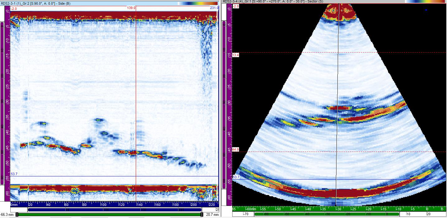
Sample data of HIC on 55mm T Vessel
Ελ. Βενιζέλου 7 & Δελφών, 14452 Μεταμόρφωση, Αθήνα, Ελλάδα |

